The way the Scooter is built means you need to take off a hell of a lot of body work and parts. Way to much in my opinion. It's pretty ridiculous the amount of stuff you need to remove but what you going to do if you need to check/clean/replace your rear brake shoes/pads. Well this is the proper way to do it according to the Service Manual used by your scooter mechanic. Please note I am not a mechanic and do this for my own benefit and reference, hopefully it also helps someone else out when I was in the same situation with little or no information on how to service the rear brakes on a Kymco People 200 S.
Thanks to XXXXXX and XXXX websites which show how to change the spark plug which got me started. I just wanted to expand on that information and take it one step further.
I highly recommend while you have the body panels off to change the spark plug while your there. It costs $5 AUD and is worth it in the long run. I change mine every 8000km/s or so. They will last much longer but for $5 AUD its worth just replacing rather than cleaning as it will help your scooter run smoother. You can use one of the Iridium version but I use the standard one recommended by Kymco, an NGK Spark Plug - CR7HSA. Hell while at it change the Oil and Gear Oil as well. It's super simple and takes very little time. Consider it a major service without valve adjustments e.t.c (Hope to figure out how to in the future). Anyway enough babbling and on with the show. Please post comments if you found this useful. :)
Things you will need:
- Phillips head screw driver
- 3/8 inch / 9.52mm Wrench
- 1/2 inch / 1.27cm Wrench
- 1/2 inch Torque Wrench (Not neccesary but very handy to have)
- 3/8 inch breaker bar with long handle (Great to get into those hard to reach places)
- Sockets 8mm, 10mm, 12mm, 14mm
- Hex key set (You only need either a 6mm or 8mm one, one or the other)
- Grease (Good quality lithium grease)
- Paper towels
- Disposable gloves
- Brake shoes if you are replacing them
- Brake Cleaner (Do not use Degreaser or Carb cleaner)
11952600
4312A-KDU-9000
4312A-KUDU-910
Other manufactures numbers:
EBC: 818
SBS: 2203
Venom: VMS-15
Quick Link Index:
- Remove the Rear Rack
- Remove Seat Bucket and 12volt socket
- Remove Battery Cover
- Remove Rear Mud Guard and Light assembly
- Remove Body Panel
- Remove Side Panels
- Remove Bottom Skid Pan
- Remove Muffler
- Remove Right Suspension
- Remove the Link Flake and Axle Spacer
- Remove part of the Tyre Guard
- Remove the Tyre
- Remove the Brakes
- Complete! Now to put it all back together again
1) Remove the Rear Rack.
Using a Hex key (6mm from memory), unbolt the 3 bolts holding the Rack to the Frame. In my case the Givi top box rack gets in the way of the 3rd bolt. Using a shortened Hex key though and some patience it came off eventually. Yes I could have undone the Givi rack but decided not to. Less screws/nuts/bolts to loose. The other 2 bolts are easy to get though. The first time I removed them I needed to use a hammer to loosen them after years of rust and grime held the bolt in place. One of the bolts and hex keys beaten up but it was the only way I could get it off. I used WD40 to try to loosen them up.So be warned!


Remove the Rack and Bolts and set aside for later.

2) Remove Seat Bucket and 12volt socket
Remove the 5 bolts inside the Seat Bucket using a 10mm socket.


Pry out the 12 volt socket with a screw driver or similar, disconnect the connector attached to the cable. Be careful not to break the connector.

Pull the bucket out being carefully not to catch the 12 volt socket cable. Pull the cable through the hole.


Put aside the seat bucket for later as well the bolts. Don't loose them.

3) Remove Battery Cover
The battery cover is under your feet when seated on the scooter. It is held on by 2 Phillips head screws. Unscrew them and apply outward pressure on the top part of the battery cover which will allow it to pop out freely.


I also disconnected the battery terminals to be on the safe side. Probably not necessary but made me feel better doing it. Remember to remove the Ground (Black) wire first and Positive (Red) wire last to avoid sparks. Do the opposite when reconnecting, Positive first and Ground next.
4) Remove Rear mud guard and Light assembly
Unscrew the 2 Rear mud guard using a Phillips head screwdriver. 1 screw on each side of the Scooter.

Undo the 2 nuts using a 10mm socket from the rear of the mud guard.


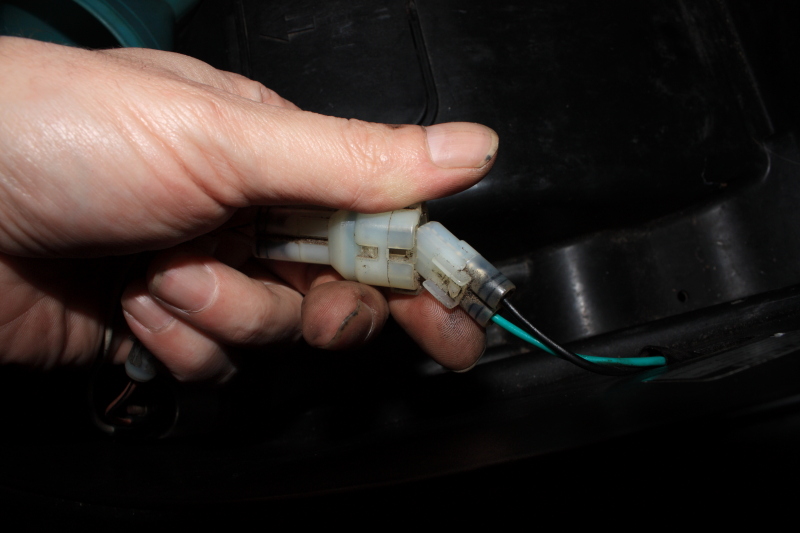
Once the nuts are removed you can pull the mud guard down and off. Be careful though as you will find a connector attached for the license plate light an will need to unclip the connector that is attached before removal. Once again be careful with the connector so as not to break it.


Set aside the mudguard and nuts for safe keeping.


5) Remove Body Panel
No screws or bolts are needed to be removed at this stage but you do need to unhook the rear of the plastic from the threaded bolts pointing outwards shown below.
From each side of the scooter, loosen the plastic tabs by gently wiggling tap them back and forth. They should just pop out fairly easily. Take care though not to snap them.


Be aware at this stage you will find another cable attached for the rear light assembly and will once again need to disconnect the connect attached.


Put aside the body panel for later. Phew, that's a lot of body panels piling up now. But more to go before we get to the tricky parts believe it or not.

6) Remove Side Panels
The side panels are easy to remove being held in place by 2 screws on each side. They are also loosely held in place by plastic tabs so be careful not to break any once again.


Yes, my right hand side panel is broken in half. But not while doing this project. It happened when some moron decided to knock my scooter over for whatever reason (I wasn't there having discovered it the next day). Thankfully that was the only real damage other than a few scratches and the two halves are still able to be screwed on. Anyway back to lesson at hand, set aside the side panels and screws for later with the rest.

7) Remove Bottom Skid Pan
Remove the 4 bolts using an 8mm socket to remove the bottom skid pan. This is needed to access the bolts connecting the muffler to the engine which will be needed later. There are 2 bolts on each side. The front ones are easy to get to with the rear ones needed a longer extension bar are long socket set to get to. It was also a PITA to take a photo of so forgive the crappy photo.
Rear bolt located at the rear behind the previous sidepanel.


Slide the plastic tabs off the metal notches for the skid pan to drop down.


Move the skid pan aside with the bolts for later.

8) Remove Muffler
Using a 12mm Socket, remove 2 bolts from the Link Flake. These were hard to get out for me and took a little time to get out. In hind sight I should have probably taken the 2 bottom bolts from the muffler off first which are attached to the engine. There possibly may not have been so much pressure on the bolts if done the other way. But this is how I ended up doing it.

This part can get tricky as you need to get under the scooter to where the muffler joins to the exhaust on the engine. So get an old cushion and get down low and find these two bolts to unscrew them. Take note that you will need to hold the muffler else it will drop onto the ground. Not good! Maybe get someone to help you how it while you unbolt it. I did it by myself without any issues.


9) Remove Right Suspension
Remove the right suspension used a 12mm and 14mm socket. The 14mm socket is used on the top and 12mm socket on the bottom. Put aside the right suspension and Bolts for later once again.


10) Remove the Link Flake and Axle spacer.
Now this is where it gets a little tricky, or at least in my case. You need a 1/2 inch wrench for this job and a 15/16 socket. I didn't have a high enough metric socket in my tool kit so used an imperial one I had which fit perfectly. Now for the tricky part, if you try to unscrew the Bolt the Tyre will also spin and you can't get it undone. Some solutions on the net suggest to use a piece of wood or steel wedged in the wheel to stop it spinning. My thinking was this could damage the wheel itself or something else as well as the paint, so I did something different. I wedged a rock under the Tyre and used some rope to tie the rear brake lever shut. Problem solved! Except now I tugged on that damn wrench with all my weight and it would not budge. I sprayed it with WD40 spray lube and gave up for the day.Next day I looked for a pipe to go over the wrench but found none. Rubber Mallet? Also found none. So if you can do this first before trying brute force hammer style, do so. Eventually I ended up wrapping a cushion around the handle of the wrench and whacking it with a hammer a few solid times. At first nothing, a few more whacks and it seemed to budge a little. Another whack and it freed up. Finally!!!!!


Now be aware when the Axle nut comes off you will have a dust seal come off which covers the bearing and protects it from dust and grime getting in. Remove it and take careful note which way it faces so you have no issues putting it back together again.


You now have access to remove the link flake from the Axle.


Take care not to knock off and loose the spacer on the front section of the link flake pictured below.


On the axle you will find another large spacer which also acts as a seal for the bearings also. Take note which way it goes in. I used a pencil to mark an arrow pointing outwards for future reference.


11) Remove part of the Tyre Guard.
The Tyre guard is the plastic cover that wraps around the rear Tyre like another mudguard preventing grime, water and dust getting in. This part just gets in the way when you try to remove the Tyre so it also must be partly unscrewed to gain access to the Tyre and brake assembly. I know, what don't you have to take off! You will need an 8mm socket to take off 2 nuts and one hex bolt which was 6mm from memory but not 100%.


Unscrew 1 of the bolts from the other side to let the plastic guard be moved out of the way.


12) Remove the Tyre.
Finally you can take off the Tyre. You will need to try to keep the plastic guard out of the way while wiggling the Tyre off the axle. It may take a little wiggle action to get going but it will eventually come off.

13) Remove Brakes.
You now have access to the brake shoes and can get an idea of how much pad material you have left on your brake shoes as well as how dirty they are. Loosen the rear brake adjuster on the left side of the scooter so that the rear brake feels very soft and loose.A word of warning: Brake pads can contain Asbestos which is potentially harmful to your health and as such you must take the appropriate action to minimise exposure to the dust. I used a Face mask, Eye wear and gloves. It's commonly said not to use compressed air or similar to clean the dust off. Instead use brake cleaner from your Auto store. DO NOT USE Degreaser or Carb Cleaner. These contain oils which are not good for your brakes if you want to stop in the future! Brakes + oil/grease = bad idea. Also be very careful not to get oil or grease on the pad material from your fingers while working. Use plastic disposable gloves and change them often.
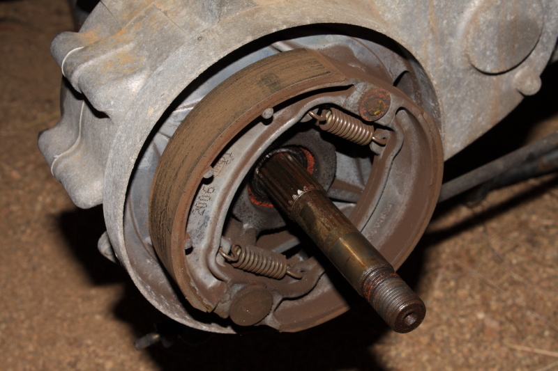

Remove the pads by pulling the pads off the Cam and Pivot of the brake. Basically pull the brakes until they turn in towards each other as if you had 2 horseshoes and pry them carefully off the cam and pivot.

Once the Brake shoes are out, use Brake cleaner and spray them till they are soaked and dripping. You want the liquid to wash away the break dust and rubbish. That's why using Brake cleaner is important as it lifts the crap off and lets it flow away from the porous brake material. Below is a Before and after shot of the brake material. I wanted to take some semi coarse sandpaper and sand them down a little to roughen them up so they bite better when braking but completely forgot to do so. I recommend you do though. Make sure to clean them with brake cleaner once sanded again.


The limit for these brake shoes are 2mm total pad material. Mine measured 3mm so still within limits but not by much. I ordered a new set of brake shoes to replace them in the future. The total cost was around $30 AUD delivered from Germany. These are EBC branded OEM brakes and hopefully should do the job just as well as the original.
Once the Brake shoes and brake dust area are cleaned out well using Brake cleaner I decide to add a tiny bit of grease to the cam and pivot area. Not much though so it doesn't work its way into the brakes. Proceed to put the brake shoes back onto the cams and pivot. I start by prying open the spring on the pivot side (The rounded side and not the flat one) of the shoes and slide the shoe onto the pivot. I then do the same on the other side behind careful not to clap my finger in there (Those springs are strong so wear eye wear in case one breaks). It may take some muscle to get on and take a couple goes to slide it on all the way, but its not to hard.

Next it's time to clean out the Drum which is located on the inner rim of the Tyre. Once again use Brake cleaner to clean the Drum out. The photos below are the before shots and I didn't end up taking any after shots but I can tell you it looked almost new once I hit it with Brake cleaner. Amazing stuff (But toxic so try not to inhale it and stay in a ventilated area when spraying as it evaporates very quick).


14) Complete! Now to put it all back together again.
Well that's about it. Once you are satisfied everything is clean, I suggest you grease up the axle, bearing seals and axle spacers lightly. Don't go nuts with the grease. Less is more in some cases. Re-adjust the rear brake adjuster screw until your rear brake lever play is less than 20mm. Also take note the Muffler was a real PITA to get back on as the side bolts no longer wanted to line up with the holes. It really was a struggle and I suggest someone give you a hand. I did it by myself but I don't recommend it. Also be aware the muffler passes through the metal frame area and not under like I struggled with. If you don't know what I mean, just keep note of how the muffler snakes through and under the scooter to the engine. It really was quite tricky to hold in place.To put it all together again just do the reverse of the instructions above and take your time, don't rush it. There are a lot of bolts, bits and body parts that need to go back on in the right order. That's why I took pictures of a lot of the bolts so you have a reference which ones go with what and where. But overall they are all different and can't really be mixed. So don't stress about it to much. The last word of warning is the Axle nut. This nut is very important as it holds the wheel on and you don't want it coming off. The torque value in the service manual states to tighten to 11.0-13.0 kg-M using a Torque wrench. I don't have one but plan to in the future. All the bolts have Torque values that you should follow. But I did it by feel due to no Torque wrench but if you want peace of mind or have access to a Torque wrench, use it. Just be aware dirt and grime e.t.c will affect the torque value to use as well as the quality of the Torque wrench and if it's been calibrated recently or stored well. Hopefully this How To will help someone else out, if not at least its a reference for myself in the future.
Wakt
Thanks! I recently bought a 2009 S200 with < 500 miles so not time for a brake job yet, but I will be doing the first part of this just to access the brake light. And saving the whole article as a PDF for future maintenance.
ReplyDeleteI was scratching my head for quite a while just figuring out how to evento the brake light - gave up, googled, and found this. Eureka!
Glad the blog post helped you to. I knew someone would find it useful one day. :)
ReplyDeleteI have a PDF of the 2007 service manual that covers the s50/s125 and s200. Email me at thisismyjunkemail99@gmail.com if you would like a copy.
ReplyDelete